
At the beginning of the fetch cycle, the address of the next instruction to be executed is in the Program Counter(PC). 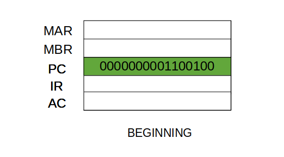 Step 1: The address in the program counter is moved to the memory address register(MAR), as this is the only register which is connected to address lines of the system bus.
 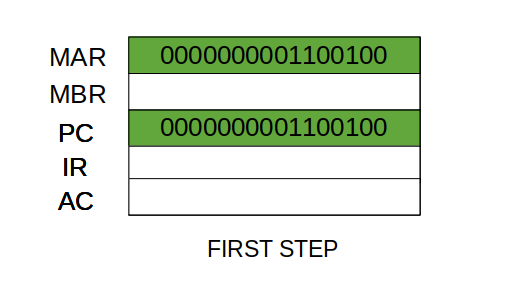 Step 2: The address in MAR is placed on the address bus, now the control unit issues a READ command on the control bus, and the result appears on the data bus and is then copied into the memory buffer register(MBR). Program counter is incremented by one, to get ready for the next instruction.(These two action can be performed simultaneously to save time)
 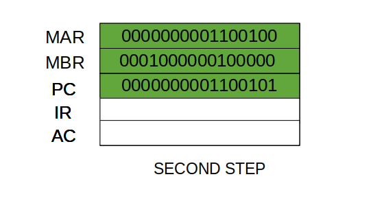 Step 3: The content of the MBR is moved to the instruction register(IR).
  Thus, a simple Fetch Cycle consist of three steps and four micro-operation. Symbolically, we can write these sequence of events as follows:-
 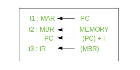 the read is performed on the address in the MAR, and the contents at that address are place in the MBR - in the same instruction the PC is incremented by one; 3) the contents of the MBR are copied to the IR. At this point the fetch cycle is complete." />Here ‘I’ is the instruction length. The notations (t1, t2, t3) represents successive time units. We assume that a clock is available for timing purposes and it emits regularly spaced clock pulses. Each clock pulse defines a time unit. Thus, all time units are of equal duration. Each micro-operation can be performed within the time of a single time unit. First time unit: Move the contents of the PC to MAR. The contents of the Program Counter contains the address (location) of the instruction being executed at the current time. As each instruction gets fetched, the program counter increases its stored value by 1. After each instruction is fetched, the program counter points to the next instruction in the sequence. When the computer restarts or is reset, the program counter normally reverts to 0. The MAR stores this address. Second time unit: Move contents of memory location specified by MAR to MBR. Remember - the MDB contains the value to be stored in memory or the last value read from the memory, in this example it is an instruction to be executed. Also in this time unit the PC content gets incremented by 1. Third time unit: Move contents of MBR to IR. Now the instructin register contains the instruction we need to execute.
Note: Second and third micro-operations both take place during the second time unit. Adapted from:
"Computer Organization | Different Instruction Cycles" by Astha_Singh, Geeks for Geeks is licensed under CC BY-SA 4.0
This page titled 4.1.1: Instruction Cycles - Fetch is shared under a CC BY-SA 4.0 license and was authored, remixed, and/or curated by Patrick McClanahan.